A Practical Guide to State Machines
In this article, we’ll examine some examples of real-world problems that can be expressed and solved using finite state machines. We’ll take the opportunity to explore some of the C#’s pattern matching capabilities an see how they come handy for implementing them. In the second part, we’ll see how to combine multiple state machines to form a cohesive workflow.
An Informal Definition
A finite state machine is an abstract device that has states and transitions between those states. It’s always in one of its states and while it reads an input, it switches from state to state. Think of it as a directed graph. A state machine has no memory, that is, it does not keep track of the previous states it has been in. It only knows its current state. If there’s no transition on a given input, the machine terminates.
For a state machine to be deterministic means that on each input there is one and only one state to which it can transition from its current state. All of the examples in this article are of deterministic state machines.

Figure 1: Representation of a door using a state machine
The state machine in Figure 1 has:
- a set of states:
Open,Closed,Locked - a set of inputs:
open,close,lock,unlock - a transition function of type:
State x Input -> State
Besides, state machines have an initial state (we can pick an arbitrary one in Figure 1) and a set of final states (which is empty in Figure 1).
Representing State Machines in C#
State machines are simply directed graphs and there’re various ways to construct one. We can use an adjacency matrix, or go with an object-oriented approach via the state pattern or encode the state and the transitions in a map structure such as C#’s Dictionary<TKey, TValue> where the keys are the states and their values are the sets of transitions from these states.
The recent developments in version 8 of C# added significant improvements in its pattern matching capabilities and the switch expressions in particular (which provided some inspiration for this article). If you haven’t checked them out, I recommend this article by Mads Torgersen, but long story short - we can now return values from switches, thus using it for conditional assignment.
We implement the state machine in Figure 1 as:
enum State { Open, Closed, Locked }
enum Input { Open, Close, Lock, Unlock }

State ChangeState(State current, Input input) =>
    (current, input) switch
	{
        (State.Closed, Input.Open) => State.Open,
        (State.Open, Input.Close) => State.Closed,
        (State.Closed, Input.Lock) => State.Locked,
        (State.Locked, Input.Unlock) => State.Closed,
        _ => throw new NotSupportedException(
            $"{current} has no transition on {input}")
	};
That’s how we “run” our machine:
var current = State.Closed; // the initial state
current = ChangeState(current, Input.Open); // Opened
current = ChangeState(current, Input.Close); // Closed
current = ChangeState(current, Input.Lock); // Locked
current = ChangeState(current, Input.Open); // throws
State Machines with Async Actions
Let’s take a look at another example. This time we’ll implement a process scheduler.
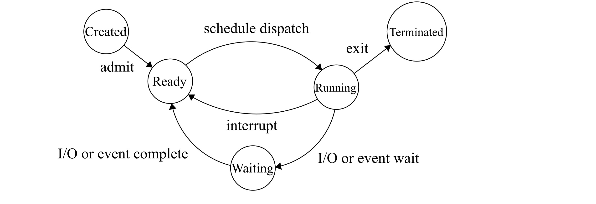
Figure 2: The states of a process
In Figure 2 we have the following sets of states and inputs:
enum State { Created, Ready, Running, Waiting, Terminated }
enum Input {
    Admit, ScheduleDispatch, Interrupt,
    IOorEventWait, IOorEventComplete, Exit
}
That’s how we implement the transition function:
State ChangeState(State current, Input input) =>
    (current, input) switch
    {
        (State.Created, Input.Admit) => State.Ready,
        (State.Ready, Input.ScheduleDispatch) => State.Running,
        (State.Running, Input.IOorEventWait) => State.Waiting,
        (State.Waiting, Input.IOorEventComplete) => State.Ready,
        (State.Running, Input.Interrupt) => State.Ready,
        (State.Running, Input.Exit) => State.Terminated,
        _ => throw new NotSupportedException(
            $"{current} has no transition on {input}")
    };
We can also create conditional transitions using the when keyword.
State ChangeState(State current, Input input, bool hasPermission) =>
    (current, input) switch
    {
        (State.New, Input.Admit) when hasPermission => State.Ready
        // ...
    };
Suppose we want to execute some transition action on state change. Keep in mind that what comes after the => is an expression. So far we were simply returning values, now we want to run some arbitrary code. The approach might not seem very intuitive, but for those familiar with JavaScript it should ring a bell. We’re going to wrap our code in an immediately invoked function expression (IIFE) using C#’s lambda syntax.
State ChangeState(State current, Input input) =>
    (current, input) switch
	{
        (State.New, Input.Admit) => ((Func<State>)(() => {
            ExecuteSomeAction();
            return State.Ready;
        }))(),
        // ...
    };
The usage of our ChangeState method remains the same.
var current = ChangeState(State.New, Input.Admit); // Ready
If ExecuteSomeAction() is a long-running operation, it would make sense to unblock the current thread by making it asynchronous. That requires us to refactor our state machine.
async Task<State> ChangeState(State current, Input input) =>
    (current, input) switch
    {
        (State.New, Input.Admit) =>
            await ((Func<Task<State>>)(async () => {
                await ExecuteSomeActionAsync();
                return State.Ready;
            }))(),
        (State.Ready, Input.ScheduleDispatch) =>
            await Task.FromResult(State.Running),
        // ...
   	};
var current = await ChangeState(State.New, Input.Admit); // Ready
Combining State Machines
In this example, we’ll see how separate state machines can interact with each other to form a unified workflow.
We’re given the task to design an online store where customers can purchase items by paying online through a bank. The system has three participants: the customer, the store and the bank, with the following requirements:
- The customer may pay or cancel at any given time.
- The store may ship items to the customer.
- The store may redeem the money from the bank.
- The bank may transfer any redeemed money (e.g. to the store).
We have to ensure that the customer cannot use one issued payment multiple times, or pay and immediately cancel, thus getting the items for free. The bank must ensure that money cannot be canceled and redeemed at the same time. The store should ship the items only when it gets the payment.
We model a separate state machine for each participant. Let’s start with the bank.

Figure 3.1: The Bank
The initial state 1 represents the situation when the bank has issued the money but has not been requested to either redeem it (by the store) or cancel it (by the customer). Once the store redeems the money, the bank enters state 3 and thus can to transfer it to the store’s account. When it’s in state 2, it restores the money to the customer’s account. The fact that we don’t allow the bank to leave state 2 prevents restoring the customer’s money multiple times.
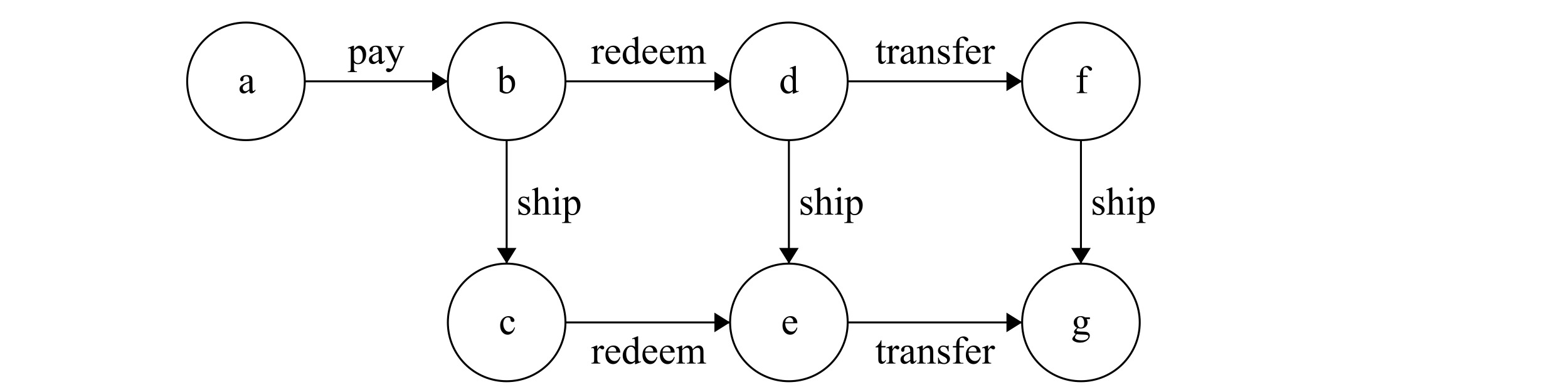
Figure 3.2: The Store
When the pay action is performed (by the customer), the store enters state b. It can then either ship the items or redeem the money from the bank. It can also ship when it has made a redeem request and before the money is transferred, or at the end when the money is transferred by the bank.

Figure 3.3: The Customer
The customer’s state machine has only one state and two input actions that lead back to the same state. This means that the customer can do anything any number of times.
Dealing with the Missing Action Inputs
To combine these state machines, they should be able to process action inputs simultaneously. We observe that some transitions are missing on some of the machines. For example, the store doesn’t have a notion of the cancel action. For the bank, pay and ship are irrelevant. To make the store “ignore” the cancel action, we simply have to add a transition from each of its states to itself on cancel.
Another potential problem would be when the customer executes pay for a second time, while the store is in state e. We need to add a transition on e to itself on pay.
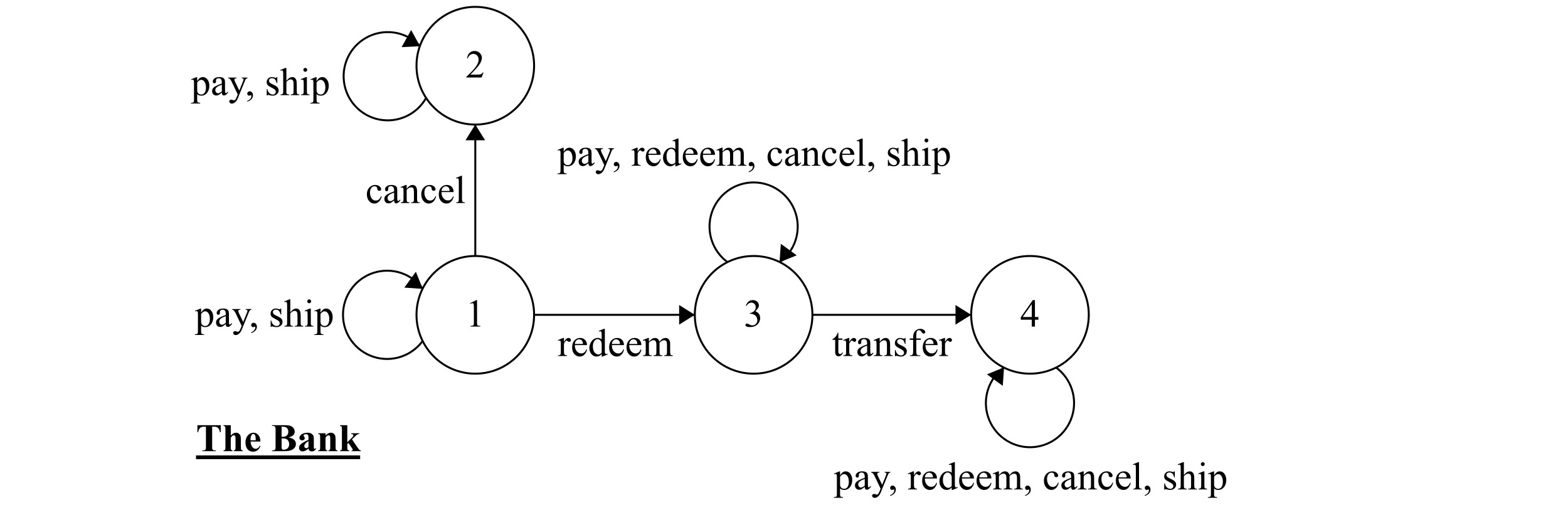
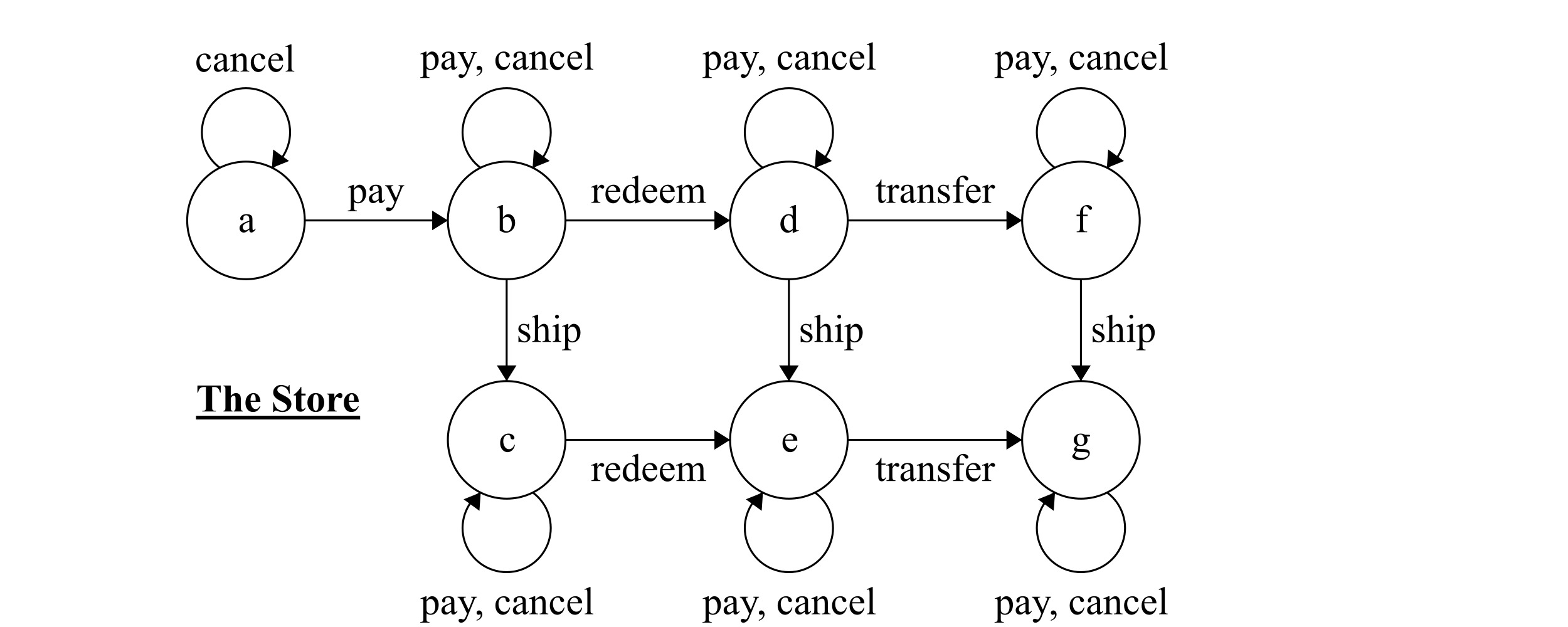

Figure 3.4: The complete sets of transitions for the bank, the store and the customer
We added self-transitions to each of the participants’ states for the actions that:
- are irrelevant to the participant (e.g. cancel to the store).
- can potentially “terminate” the machine (e.g. executing pay while the store is in a state other than
a)
Keep in mind that the behavior of the state machines does not depend on who initiates the action. The actions are independent events that occur in our system. The complete state of the system is a combination of the current states of these three automatons. On each event they either traisition into a state of their own or stay in the same state.
Constructing the Product
It’s still not quite obvious how the states in the store and the bank interact. To see this more clearly, we need to construct the product of those state machines. The product is a state machine itself, and since the customer automaton only has one state, the states of the product are pairs of states from the bank and from the store.
For example, the state (3,d) represents the situation where the bank is in state 3 and the store is in state d. The total amount of states is 4x7=28. We group them in a table where the row corresponds to the state of the bank and the column to the state of the store. The initial state is the pair, both items of which are initial states of their respective machines - in our case (1,a).
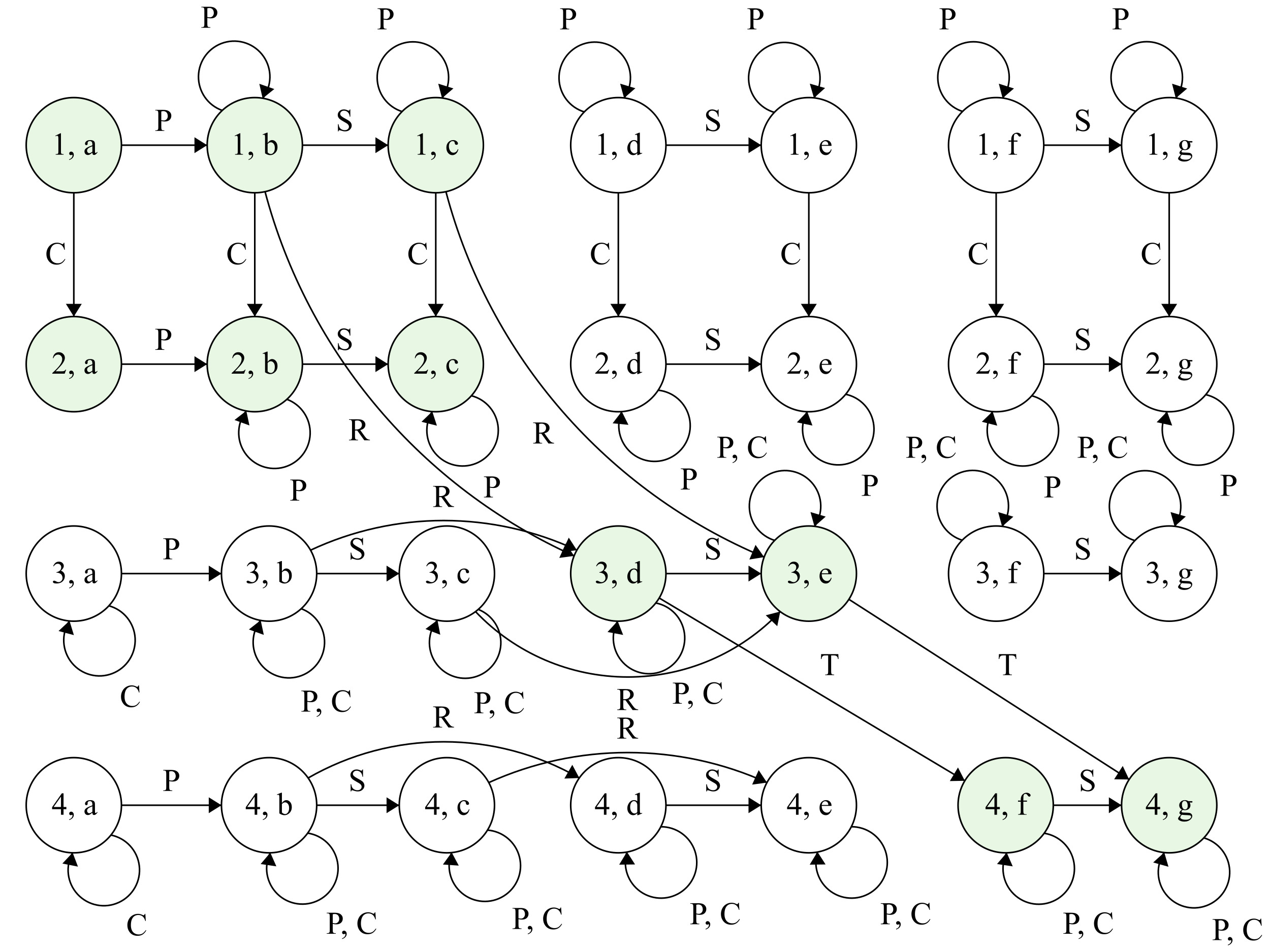
Figure 3.5: The product of the bank's and the store's state machines; the reachable states are marked in green.
P - pay, C - cancel, R - redeem, S - ship, T - transfer
We’ve drawn all of the state pairs and the transitions amongst them. We can now clearly see how the inputs affect the system as a whole. For instance, on pay, the store goes from a to b, whereas the bank stays put, therefore, change_state((1,a), "pay") -> (1,b). From state (1,b), on redeem, the store goes from state b to d and the bank from 1 to 3, therefore, we end up in change_state((1,b), "redeem") -> (3,d).
Eliminating the Unreachable States
We observe that not all states are reachable from the initial state (1,a). For example, we cannot go to (1,g) where the store has shipped the goods after the money is transferred, but the bank is still waiting for a redeem - this makes no sense! We’ve modeled our system such that a case like this cannot occur. We also found a flaw in our logic, that is, when the machine is in (2,c), the items have been shipped but the money hasn’t been transferred because the customer has issued cancel.
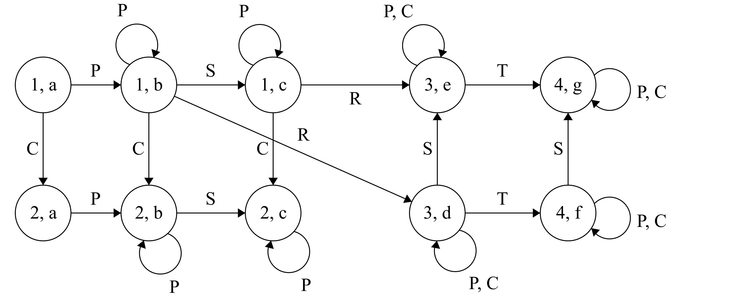
Figure 3.6: The combined state machine for the bank and the store.
P - pay, C - cancel, R - redeem, S - ship, T - transfer
After discarding the unreachable states and all of their outgoing transitions, we end up with a much clearer picture, that is, a state machine that is easy to understand yet encodes complex business logic.
Conclusion
In this article, we’ve informally introduced the concept of finite state machines and a new way to implement them in C# using pattern matching. We examined a scenario with multiple participants whose behavior we can model as state machines. We learned how to combine those state machines and establish a unified workflow. This made it much easier to reason about the soundness of our system and depict its possible use cases.
State machines present a powerful way to express application logic. That way, seemingly complex set business rules can be reduced to something easy to comprehend, extend and modify. They are no silver bullet though. Not every domain is suitable to be modeled in such a way. When we have to deal with a system which oftentimes involves human interaction and its events do not always occur in a prescribed order, state machines are a powerful tool in our toolbox - well worth exploring.
References and Further Reading
- “Introduction To Automata Theory Languages, and Computation” Hopcroft, Ullmann, Motwani; Chapter 2 - Finite Automata
- Do more with patterns in C# 8.0
- Robust React User Interfaces with Finite State Machines
- Finite State Machine Designer
- stateless - a state machine library for .NET
- workflow-core - a .NET workflow engine